Safety
Powering Up! It’s an Uncertain Time (July 2024)
Minimizing non-essential personnel in the vicinity of a rocket is a recommended practice when arming/safing electronics that control energetic events. Two people is the desired number with one person being the “doer” that arms/safes the electronics and one person being the “reader” who is verifying accomplishment of checklist items. Sometimes a third person is necessary; an example is someone to steady a ladder that supports the doer.
Computers and electronic systems may accidently fire energetic devices for several reasons during startup or shutdown. Causes include software initialization that may not immediately arrive at a stable state, establishment of logic level voltages, and a “horse race” when timing events may not proceed in the required order. The nature of the arming/safing process requires at least one individual to be in close proximity to the rocket.
The NAR Safety Committee suggests that individuals arming/safing rockets keep their heads at least 18 inches from the rocket during arming/safing. The issues with this recommendation are that some electronics are not sufficiently loud or distinctive to be heard when sounding out their prelaunch status or that aligning a tool or pin with a device within the rocket requires one to look through a small hole into the rocket.
Medical type stethoscopes can be purchased for under $20.00 and can assist in listening for electronics’ prelaunch status. 3D printed “funnels” attached to screw switches or pull pin guides within the rocket can assist with aligning screwdrivers and pull pins with their respective devices. External switches are another alternative. Visual arming indicators on circuit boards are a challenge since displays and LEDs are often not visible from afar.
Personal protective equipment (PPE) is highly suggested during arming/safing procedures. The most vulnerable body parts are the eyes and face. At a minimum, safety glasses should be used by personnel performing arming/safing operations. A full-face shield is a better approach. Sections might consider purchasing one or two face shields as part of their range equipment.
NAR Safety Committee Chairman
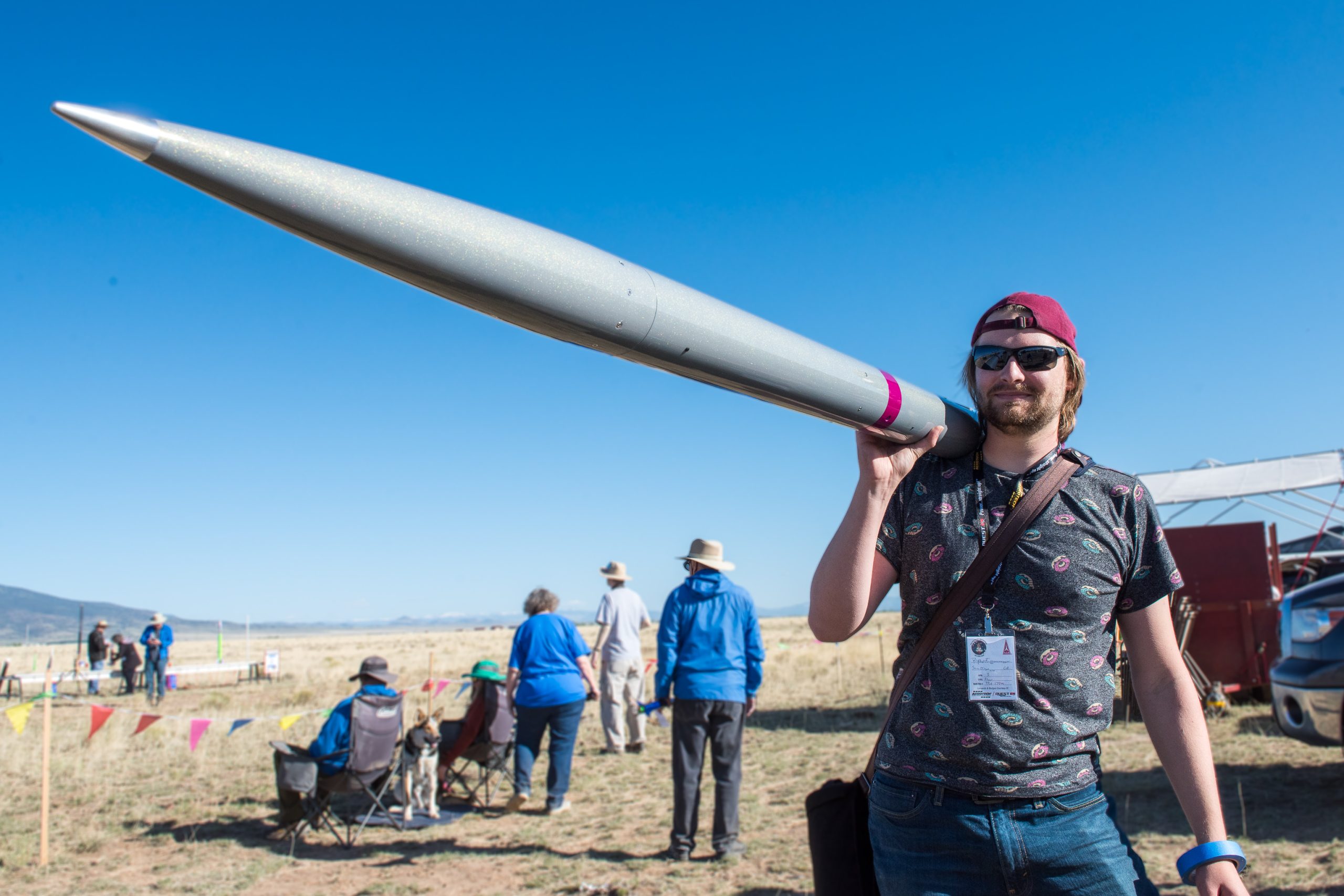
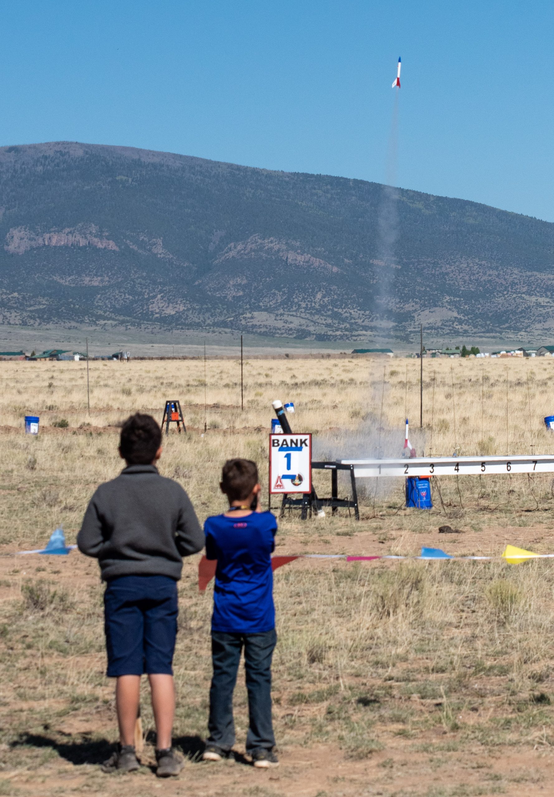
Launch Rail/Rod Length (June 2024)
Flight safety reviewers and check in officers will often ask for the high-power rocket velocity as it leaves the launch pad guidance. A threshold value exceeding 50 feet per second is often desired with some launch operations adding an objective requirement of 100 feet per second (to account for winds and less than ideal static stability). An important element in calculating the launch velocity is knowing the usable rail/rod length at the launch pad being used.
The “net” rail/rod length needs to considered. The “gross” rail/rod lengths often quoted for launch pads are typically the uninstalled rail/rod lengths that do not account for the unusable section. The unusable section includes the portion of the rail or rod under the rail/rod standoff. The other “net” measurement depends on the rail guides’ or tubular launch lugs’ positions on the rocket. For a rocket that uses two rail buttons, the launch rod/rail does not provide effective guidance once the upper rail button exits the rail. Rockets that use two short (each less than one lug diameter in length) launch lugs can be considered to have the same issue.
As an example, let’s assume an eight foot (96 inches) uninstalled launch rail. Probably six inches of this rail are unusable because of its attachment to the launch pad and the location of the blast deflector and rocket standoff. We are going to place a five foot tall rocket on this rail. The forward rail button is located 18 inches from the back end of the rocket. The net length of our launch rail is now six feet (72 inches) since the rocket will lose launch guidance as the forward rail button exits the rail.
NAR Safety Committee Chairman
Launch Pad Activities (May 2024)
A rocket, in the vertical position on the launch pad, ejected its nosecone at a recent launch while a person on a ladder was working on the rocket. Fortunately, there were no injuries from this incident. The person was using a file to enlarge an access hole on the rocket to allow arming of electronics. It is assumed that the individual contacted the internal electronics with the file and activated a charge. The incident, with a potential for significant injuries, could have been prevented.
Assembly of the rocket on the ground should have verified that arming switches had access and could be safed or armed at the launch pad. Part of that testing should have identified the required tools and that the tools were listed in all checklists that armed or safed electronics.
Range personnel should not allow activities other than those required to launch, arm, or safe the rocket to be performed at the launch pad. This is especially true with the rocket in the vertical position. Only activities identified in the applicable checklists should be permitted. Additionally, no work should be performed by a person on a ladder except that identified by checklists.
If work or troubleshooting needs to be performed on a rocket it should be returned to its preparation area (with all electronics safed and the igniter removed from the rocket motor). If structural work is being performed, any energetics should be disconnected from the electronics, removed if possible, and/or batteries should be disconnected. If electronics troubleshooting is required, try to substitute an inert or less energetic device in place of the flight energetics. Consider the hazards from accidental activation of energetics (again, the motor igniter must be removed) and reduce personnel accordingly, clear potential trajectories for separated components, and use proper personal protective equipment.
Steve Lubliner
NAR Safety Committee Chairman
 Chute Protectors (April 2024)
Nomex parachute protectors and shock cord sleeves are typically used on high power rockets instead of wadding. The parachute protectors and sleeves provide better protection of recovery components than wadding and take up significantly less volume than baffle systems. Flyers do need to exercise caution when rigging parachute systems with protectors and sleeves to prevent parachute deployment failures.
Parachute protectors should not be placed on parachute suspension (shroud) lines. The problem is that the “button hole” in the protector can slide along the suspension lines and reef the parachute preventing the parachute from opening. Instead, parachute protectors should be installed on the shock cord. In a typical parachute “mortar” setup, my practice is to place the chute protector over the shock cord near the attachment point closest to the pyro charge(s) but far enough away to clear the body tube at deployment. The chute protector is folded around the parachute and majority of the shock cord to create a ”taco” or “burrito”. The protector should unfurl and release the parachute and remainder of the shock cord as it clears the body tube. Once the chute protector clears the body tube its job is over as the compartment hot gases are being vented to the atmosphere. On my larger rockets I typically use a Nomex sleeve over the shock cord near the charges for heat protection. I place the chute protector at the end of the sleeve and enclose the remaining shock cord and parachute within the chute protector.
In any case, test your parachute deployment by walking the separated rocket sections apart. Recovery systems should easily slide from their compartments and the parachutes should fall out of their protection as the shock cord is extended. If either the parachute protector or sleeve is sliding on the shock cord consider a tie wrap (make sure not to leave sharp edges) or some means of restraint to stop the movement.
Steve Lubliner
NAR Safety Committee Chairman
An Answer to Forgetfulness—Checklists (March 2024)
 The upcoming flying season will see many high-power rockets of considerable complexity flown. In April, collegiate teams will compete in NASA’s Student Launch Initiative (SLI). In June, collegiate teams from around the world will compete at the Experimental Sounding Rocket Association’s (ESRA) Spaceport America Cup (SAC). And, with improving weather, the number of high-power certifications will increase. The SLI and SAC competitions, as well as Level 3 certifications, require the use of checklists. The use of checklists is good practice for all complicated rockets even when not required.
Consider using a minimum of three checklists. The first covers the flight preparations; it might include installing energetics, verifying power source status, and installing flight expendables (e.g. shear pins). The second checklist covers launch pad operations that may include arming procedures and final visual inspections (e.g. removing lens caps and protective covers). The launch pad operations checklist should also include the steps necessary to safe a rocket if it requires removal from the launch pad or troubleshooting. The final checklist covers recovery operations including verification of no live energetics, capturing volatile flight data, and safing systems. This checklist should also contain additional items in the event of a non-nominal recovery.
Checklists should focus on key tasks that are often overlooked. Do not spell out all the details (unless a task is highly complex) and emphasize tasks that cause failures. It may be helpful to include the expected parameters where appropriate instead of relying on memory. For example, chirp patterns for recovery electronics might be identified. Identifying potentially hazardous tasks is also a good practice in all checklists. Follow a predictable order when creating your checklists.
Printed checklists offer ease of handling and readability in bright sunlight. Consider a “Read-Do-Confirm” model for performing a checklist. Read the checklist item, perform the task, and confirm accomplishment. Having two people perform the checklist, e.g. a reader/confirmer and a doer, is suggested.
“Checklists not only offer the possibility of verification, but also instill a kind of discipline of higher performance.” Credited to Atul Gawande, MD, “The Checklist Manifesto”.
Steve Lubliner
NAR Safety Committee Chairman
What’s in a Name? A Possible Flight Failure (February 2024)

Image Credit: NASA
 Drones at Launches (January 2024)
A common question is whether drones may be operated at a launch. The term “drone” often refers to remotely piloted, multi-rotor aircraft, but could be other remotely radio-controlled model aircraft.
In general, the NAR insurance specifically does not cover any accidents resulting from the operation of powered drones or other model aircraft vehicles. The NAR does, however, consider radio-controlled rocket gliders and payloads carried by rockets to be a part of a rocket, which falls under our insurance coverage when flown in accordance with our safety codes.
It is up to local launch organizers and RSOs if they will allow drones or other model aircraft to be operated at a launch. The NAR recommends that these local policies should be part of any pre-launch announcements, advertisements, and registration notifications, as well as pre-launch fliers’ briefings. If drone or other model aircraft operations are permitted, the local club should establish and communicate to participants the areas where drone or other model aircraft operations will be allowed and when these models will be permitted to fly during launch operations. Local club leaders are also encouraged to check with landowners regarding the use of drones or other model aircraft on their property.
A general safety recommendation is that drone and other model aircraft operations are only allowed away from the flightline, parking areas, and other locations with people/spectators present.
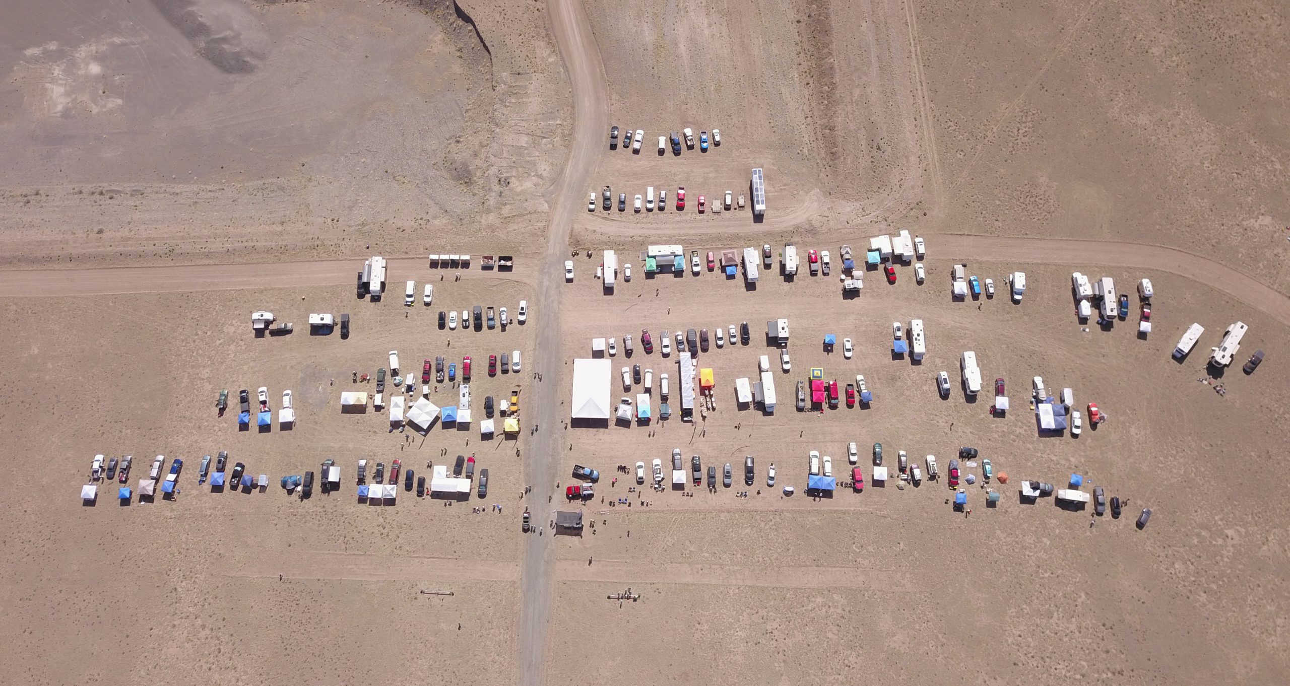
 Launch Pads (December 2023)
The launch pad provides the initial guidance for a hobby rocket until it has attained sufficient velocity for its fins to provide stability. Launch pad guidance includes keeping the pointy end up and providing the initial direction for the rocket’s flight. An inadequate launch pad can cause an unpredictable rocket trajectory.
The launch pad needs to be sufficiently rigid and stable to support the weight and size of the rockets planned for launch. Launch pads intended for larger models are often built from aluminum and/or steel for sufficient rigidity. Launch pads should have as large a footprint as practical to provide stability. Provisions for staking the launch pad into the ground can improve stability. An alternative is sandbags over launch pad legs but be aware that the rocket plume can melt or burn the plastic used to contain the sand. If you are using “launch heads” intended to mount over “green stakes” or rebar, verify that the mounts are firmly embedded into the ground.
It is suggested that the launch pad to have provisions for adjusting the launch angle. The NAR requires launch rods and rails to be angled five degrees or more (not to exceed 20 degrees) away from the flight line to avoid overflying people. If the launch pad is not angle adjustable bring wood 2x4s, bricks, or similar items to place under launch pad legs to adjust the launch angle.
Once the launch pad is set up do a pull test on the rod or rail. You should not be easily able to pull the rail/rod out of the launch pad. If launch heads are used, try to pull the launch head from its support. Inspect the rods/rails for cleanliness (no excessive exhaust residue or corrosion) and bends when doing the pull test.
Have a happy and safe new year!
Steve Lubliner
NAR Safety Committee Chairman
Model Rocket Shock Cords (November 2023)
“Separation” is a word heard too often on the model rocket flight range, especially when novice flyers are launching. It typically means that the rocket has separated into two parts, one of which does not have a recovery device. A “shock cord” is a rocket component that ties rocket sections together. Some careful design and preflight inspections can minimize the likelihood of in-flight separations caused by shock cord failure.
Model rocket shock cords have historically been 1/8” to 1/4” wide rubber or sewing style elastic. Traditional guidance for shock cord length has been a minimum of one rocket length past the separation point. One way to improve the shock cord durability is to increase its length. In general, a shock cord two to three times the model rocket length will be less prone to failure (while a too long shock cord is generally not a problem it can tangle and complicate recovery system packing). Another way to improve shock cord reliability is to use a non-elastic shock cord, e.g. Kevlar cord. Kevlar cord is more resistant to the chemical and thermal environment caused by the ejection charge within the body tube. A caveat when using Kevlar cord is that during adverse recovery conditions (early or late ejection) it can cut the body tube in a failure mode called a zipper.
Another failure point is the knot used to secure the shock cord to a screw eye. If the “tail” (the short length that exists when you tie the knot) is too short the knot may untie under load. A drop of wood glue will help secure the knot. Do not use super glues to secure the knot because the super glue chemistry can attack rubber.
The most important step to prevent separations is a preflight inspection and pull test. Look for cracking on stretched rubber shock cords, heat damage, and brittleness; replace the shock cord if you see any of these. Do a pull test before packing your parachute. The goal, if the shock cord is going to fail, is to fail it on the ground.
Steve Lubliner
NAR Safety Committee Chairman
The most severe external environment for your rockets is probably in your car.
Hot Stuff (October 2023)
Exposure to high temperatures can have adverse effects on your rockets. The most severe internal environment, because it is a longer lasting environment during flight, is the rocket motor case temperature. Per National Fire Protection Association (NFPA) code NFPA 1125, rocket motors up to 160 Newton-seconds (N-sec) total impulse are permitted to have a case temperature up to 200C (392F) and rocket motors that exceed 160 N-sec total impulse are permitted to have a case temperature up to 220C (428F). Ejection charges may be hotter but last for a shorter duration.
The most severe external environment is probably in your car. Portions of a closed car interior on a 38C (100F) day can reach over 66C (150F) within an hour and rockets may be exposed to this environment for several hours. Even rockets that are in the open, e.g. on a table in direct sunlight, can be warmed to temperatures up to 22C (40F) hotter than the ambient air temperature. Aerodynamic heating is typically not an issue except for multi-Mach rockets.
Adhesives can soften and weaken at elevated temperatures. Epoxies heated above their glass transition temperature will be become rubbery (but return to their glassy, solid state upon cooling). For example, the glass transition temperature for West Systems 105 epoxy resin and its hardeners is around 55C. Plastic materials may lose strength and warp at elevated temperatures. An example is PLA polymer commonly used for 3D printing. Its glass transition temperature is typically 60C to 65C.
There are some preventative actions the flyer can take. Consider the temperature properties of your adhesives and building materials and use them in appropriate locations (no hot melt adhesives, please). Keep your car as cool as possible (e.g. open windows and sunshades when parked). Keep your rockets out of the direct sun; an emergency mylar blanket can be an effective sunshade. Painting your rockets in lighter colors will also help (during car testing a dark colored car was over 8C (15F) warmer inside than a lighter colored car after a couple of hours).
Steve Lubliner (from Tucson, Arizona where it’s a dry heat, like an oven)
NAR Safety Chairman
Rocketry’s Biggest Variable – Weather (September 2023)
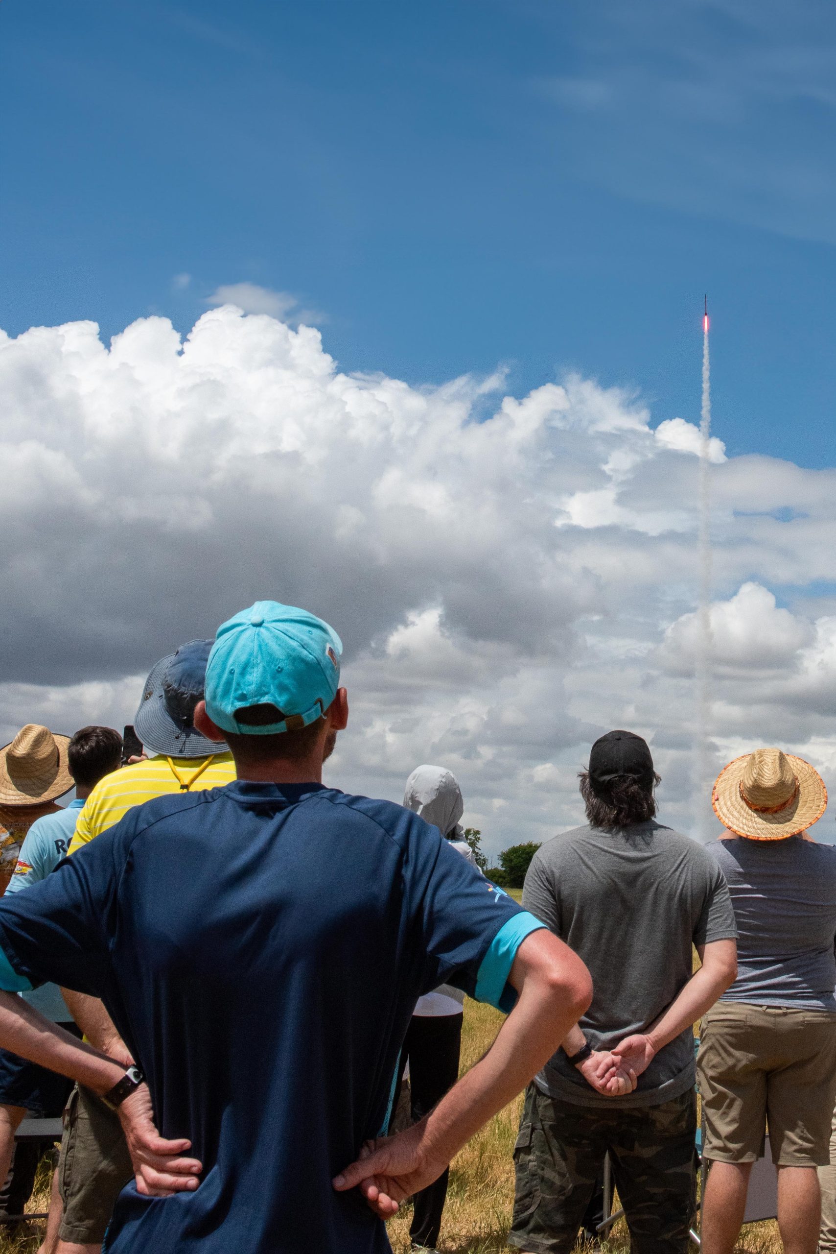
Weather is the greatest variable that affects our ability to fly rockets. Winds are perhaps the greatest factor in deciding when and where to fly because they affect the boost trajectory and the landing location. Both the model and high power safety codes prohibit rocket launches when the winds exceed 20 miles per hour.
An element of weather that is sometimes overlooked is cloud cover. Both the model and high power safety codes state that rockets may not be launched into clouds. The Code of Federal Regulations (CFR), Title 14, Volume 2, Chapter I, Subchapter F, Part 101, Subpart C, Section 101.23, “General Operating Limitations”, Item 4, states that you must operate an amateur rocket (includes model and high power rockets) in a manner that it does not create a hazard to persons, property, or other aircraft. If you cannot see an aircraft or the aircraft cannot see the rocket there is a potential hazard. Section 101.25, which defines operating limitations for Class 2 high power rockets states that you will not operate high power rockets at any altitude where clouds or other obscuring phenomena of more than five-tenths coverage prevails. In laypersons’ terms – not more than ½ of the sky has cloud coverage. This means that you will not launch your high power rocket into the hole in an overall cloud cover. Prudence should govern continuing launch operations in spotty or varied coverage, even at less than 50%, given the unpredictable nature of HPR trajectories.
Other weather elements to be considered include rain, dust, and lightning. Rain and dust generally degrade visibility and Section 101.25 requires horizontal visibility in excess of five miles. Lightning is a hazard to all personnel at the launch. If lightning is in the area all personnel should seek protective shelter (typically a vehicle).
Fly Micro-Maxx models on the foggy days.
Stephen Lubliner
NAR Safety Committee Chairman
 New Flyer Assistance (August 2023)
New rocket flyers, especially youngsters, come to our launches with expectations of making high holes in our skies. Experienced rocketeers need to assist these flyers to make safe and successful flights. Offer to help while the model is being prepared for flight.
Offer suggestions on how to pack the recovery system. Confirm that flameproof wadding is used. Verify that the shock cord is fully secured to the rocket body and nosecone. Make sure that the nosecone is neither too tight or too loose. If you come equipped with some simple supplies like sandpaper, masking tape, and baby powder you can easily address many recovery system problems.
Motor retention is a concern. New flyers often do not adequately friction fit motors in rockets without motor hooks. If motor hooks are installed, make sure that the hook fits against the motor and behind the rearmost part of the motor casing. Push on the motor to make sure that the motor mount is actually secured within the airframe.
Examine the launch lug to be sure it is securely mounted, parallel to the rocket’s long axis, and not interfering with other airframe parts. Gently push on the fins to confirm they are tightly mounted to the body tube with no cracking of joints or fin materials. It helps if you have some CA “super glue” and accelerator to make quick field repairs.
You have two objectives in the above activity. First, you want the rocket to fly safely. Just as important, is the need to create a learning moment for new flyers so they return to future launches. Explain why fixes are needed and what can be done to build better rockets.
Steve Lubliner
NAR Safety Chairman
 Pointy Things (July 2023)
Rocket nosecones and fins can be pointy things. This is great for poking holes in the sky but what about when rockets are being handled on the ground? Many events have folks standing in lines for inspections and launch pad access. A complication is that the folks standing in line are not just adults but also children. The heads of these shorter participants may be in line with the nosecones and fins of horizontally carried rockets.
There are several ways to mitigate the risk of an unfortunate close encounter. Smaller rockets may be carried closer to the flyer’s body to minimize accidental contact. Carrying rockets vertically, nosecone up, can help avoid nosecone contact but fins may still be a problem. Keep in mind that scale models may have projections, e.g. simulated antennas, that are also a poke hazard. The use of padding on nosecones and fins, especially on larger rockets, should be considered. Tennis balls and pool “noodles” can be great point and edge protection. Try to keep the larger rockets out of inspection and pad access lines. One way to do so is a “roving” check-in inspector who can go to flyers’ preparation areas to check in larger projects.
Rockets are not the only pointy things on the launch field. Launch rods for should be carried vertically. Flyers should use the launch rod cap provided with some launch controllers. Expended rocket motors can be used as launch rod caps; painting them a high visibility color is suggested. Mounting the launch rod tip higher above ground can minimize the eye hazard but makes rocket placement on the launch pad a challenge for shorter participants.
Still standing in line,
Steve Lubliner
NAR Safety Committee Chairman
 Recovery Hardware (June 2023)
High power rockets often experience high shock loads during recovery deployments. Many rocketeers now utilize nylon or Kevlar webbing to provide adequate shock cord strength during the deployments. A commonly observed weakness during safety inspections at the Student Launch Initiative and the Spaceport America Cup is the adequacy of the hardware used to connect the shock cord to the rocket.
Bent wire eyebolts often provided with high power rocket kits may not always be the safest component because they could straighten out and release the shock cord when exposed to high shock loads. The bent wire eyebolts can be used if the “eye” is welded closed but, unless space is a problem, better alternatives exist. Forged eyebolts are an excellent alternative often available from hardware and home improvement stores. “U-bolts” are another acceptable alternative and have an advantage that they cannot rotate free from the rocket. Some form of thread lock is recommended for all of the threaded fasteners used to retain the connection hardware and is especially important if the termination can rotate, e.g. eyebolts. Thread lock methods can include thread lock compounds, e.g. Loctite, nuts with nylon locking inserts, staking nuts with epoxy, and safety wire.
Often overlooked is the use of large diameter “fender” washers or similar parts (e.g. the rectangular plate often provided with U-bolts) underneath the anchor device. The intent is to distribute the loads on the bulkhead to which the shock cord is attached. Small diameter washers normally placed under the threaded fastener concentrate the shock load stresses over a smaller area. This can cause localized cracking/deformation of the bulkhead and, in severe cases, bulkhead failure.
Steve Lubliner
NAR Safety Chairman
Flight Simulations – They need the correct inputs! (May 2023)
Simulation programs to predict hobby rocket performance have been available for over 50 years. Fliers often refer to their simulation results to justify safe launch performance, stability, and apogee predictions.
Users need to provide correct inputs to get accurate flight predictions. The expected ambient temperature and local ground elevation (or ambient pressure) at the launch site need to be entered. The planned launch rod or rail length needs to be entered to properly calculate the exit velocity from the launch pad. The actual launch weight of the rocket needs to be used in the simulation to accurately evaluate acceleration and apogee performance. Rockets experience weight “growth” because finishing materials, adhesives, and small items (e.g. quick links, switches) were not accounted for. Inaccurate material descriptions within the parts list can significantly change the calculated weight. A good discipline is to weigh all components being used in the rocket and either verify the program calculations or utilize the mass overrides many programs will allow. Program calculations for the center of gravity (CG) should be taken as suggestions since recovery components will shift within the airframe during acceleration. The CG is easily verified during rocket inspections by determining where the rocket balances. External part dimensions and placements need to be as accurate as possible to permit accurate center of pressure (CP) calculations and the subsequent evaluation of static stability.
Some programs will allow the user to override the calculated coefficient of drag (CD). While determining the actual CD is somewhat of an art and is often refined after test flights, users should consider if the CD seems reasonable for the model’s finish and construction.
Stephen Lubliner
NAR Safety Committee Chairman
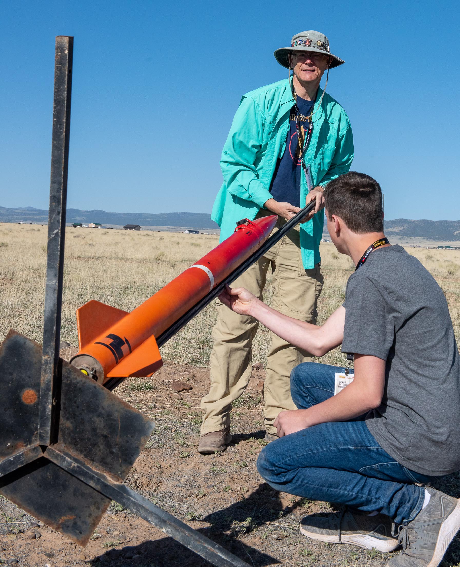
Igniter Installation (April 2023)
One of the differences between model and high power rocket operations concerns rocket motor igniter installations. The NAR Model Rocket Safety Code makes no mention of when or where igniters may be installed in the rocket motor(s). Most NAR sections permit model rockets to be presented at check-in with their igniters installed. This is considered a safe practice when using igniters produced by the manufacturers of model rocket motors. Consult the Range Safety Officer at your launch if you intend to use igniters that require very low currents or are static sensitive for any special use precautions.
The NAR High Power Safety Code states that the motor igniters will be installed after the rocket is at the launching or prepping area. Some additional steps are suggested prior to installing the rocket motor igniters. First, the rocket should be mounted on the launch pad and positioned vertically. Second, all internal avionics, including payloads if installed, should be powered, confirmed to have passed any power-on self-tests, and are indicating flight readiness. Finally, the number of personnel at the launch pad should be the minimum required to install the igniters. The igniters may be installed at this time (staged rockets are a separate discussion due to likely complexity or sensitivities of the igniter installation).
The launch pad controllers should be verified to be in a safe state prior to connecting the ignition leads. If the controller has no audible/visual indicators of safe status briefly contact the leads and observe no sparks. Once satisfied that the leads are not energized, connect them to the igniters and clear the launch area of all personnel.
Steve Lubliner
NAR Safety Committee Chairman
Shelf Life (March 2023)
Many of us are familiar with the “Use Before” dates on our food stuffs. What we may not think about is the use before dates or shelf life on the materials that we use for building models. Adhesives may age by solvent evaporation and/or polymerization of their ingredients. This can affect their strength or viscosity and create application problems. They may not properly cure and achieve the structural strength expected when used. Paints may separate, color shift, have solvent evaporation, and some chemistries may also polymerize. In addition, spray cans may leak their propellant gas over time. Like adhesives, these issues can create curing and application problems.
Typical spray paints, e.g. Krylon and Rustoleum, have a manufacturers’ specified shelf life of two to three years. A common 5 minute epoxy by Devcon has a shelf life of three years, West Systems epoxies have “expiration dates” two years after manufacture, and Titebond III has a minimum shelf life of one year. Your experiences may be different. Environmental conditions, typically storage temperature and humidity, will affect shelf life. If the storage environment is comfortable for you, it will probably extend the shelf life of your products. Also, most shelf lives are stated for unopened products. Exposure to oxygen and humidity from broken seals can shorten shelf lives. Aerosol cans, once used, are more likely to leak their propellant over time.
Some materials will allow the addition of solvents to thin them to ease application if they have become too thick to apply. Agitation to remix separated ingredients may help. Follow the manufacturers’ recommendations. The best strategy, if in doubt about a paint or adhesive, is to apply a sample to spare or scrap items and evaluate whether it is acceptable.
Steve Lubliner
NAR Safety Committee Chairman