Igniters
How to Make “J” Igniters
by Jay Marsh
Here are my initial instructions for making the “J” igniters. These are designed to plug into SIP electronic sockets that are built into the head of a piston launcher, whether floating head or fixed-head.
“J” IGNITERS – Bill of Materials:
- Apogee Dip It pyrogen
- .005” to .009” Nichrome wire (26 to 28 gauge)
- .020” X .020” square plastic rod
- Dual SIP socket (Mouser 575-113132)
- G-Flex epoxy and microballoons
- CA glue
The picture above shows the basic steps to making a “J” igniter from the components through the dipped and finished igniter. Through the use of a standard SIP socket the “J” igniters are easily hooked up in a piston by pushing into an identical socket in the piston. This makes for easy replacement of an igniter should a miss-fire occur which may have just cost you the Gold Medal.
The piston head is made with a permanent SIP socket glued into the head and another SIP socket inserted and taped together. This gives the ability to replace the socket in the head of the piston when it gets grubby. A whip lead with a socket soldered to the end can also be made to fit these igniters if not using a piston giving a easy way to hook up the launch system clips. This whip is also very helpful when testing the igniters for continuity during the manufacturing process.
1) Cut the nichrome wire to the length desired. Calculate 1 5/8” starting for a 3/8” tall igniter and add 1/4” for each additional 1/8” added to the length (ie. 1/2″ igniter = 1 7/8” nichrome, 5/8″ igniter – 2 1/8″, and so on).
You will have to adjust and add an additional 1/4″ for the .005” nichrome wire because you will have to double the wire over a second time to fit it properly into the socket. An alternative is to lay the thin wire over the socket hole and slid a larger, stronger piece of wire over and push all into the socket. The thinner the wire the less amount of power it will take to ignite, HOWEVER, if you are using a strong power supply such as a 12V battery you will want to use thicker wire igniters because the small wire can heat so quickly it may break somewhere there is no pyrogen and you will have a miss-fire.
2) Cut a piece of the plastic rod the length you want the igniter to be and cut a double SIP socket from the strip by cutting at the third socket wasting that socket and clean up the ends of the SIP. The reason for this is if this socket were to be soldered into a circuit it wouldn’t matter that the plastic housing was broken at the end but for this purpose the end needs to stay intact so separating the SIP away from the sockets is the only way to be sure of not damaging the SIP and allowing the SIP sockets to work lose.
3) Bend the nichrome wire in the center with a smooth, tightly curved bend until the sides of the wire are parallel, the same length, and about the width of the plastic rod.
4) Position the plastic rod between the wire leads and leave approximately 3/32” of the nichrome loop exposed. Apply CA to the sides of the plastic rod enough to tack the wires down to the plastic rod.
5) Bend the wires sticking out over themselves with a pair of needle nose pliers leaving about 1/4″ hanging below the plastic rod. For the thin .005” wire you will do this twice.
6) Insert the wires into each socket well down into the socket until the plastic rod is touching the SIP socket and then form it all to be straight and in the center of the socket. For the thin wire stick a piece of the thicker nichrome also in and trim. This will take up additional room in the socket cup and assure you of a good connection.
7) Make all of the igniter bases you are going to make in this batch by repeating steps 1 through 6.
8) Mix up G-Flex epoxy and add microballoons to stiffen the mix considerably until the mix is a thick putty.
9) Place the igniter on the end of a balsa stick and form a large fillet of epoxy around the socket, igniter and up to the bare loop at the head. Once coated, stick this into a piece of sheet balsa to support it while the glue cures. When you add an igniter to the sheet to cure, using a mixing cup, turn the board over so the igniters are hanging down so the epoxy doesn’t puddle off the socket.
10) Continue through steps 8 and 9 until all igniters are supported with epoxy and let cure.
11) Reform the loop, if necessary, to be a very small loop that is about .020” across but be sure the sides don’t touch each other.
12) Using a brass hammer on and anvil. Hammer the end of the loop flat but still intact. Use caution with the thin wire as it will break easily. You are trying to flatten the wire and increase the resistance where the pyrogen is going to be located so when power is applied this loop will heat first and set off the pyrogen inside the motor.
13) Using a DVM check continuity on the igniter and put back on the balsa sheet. If an igniter does not test positive then simple discard it. It’s not worth finding the cause and trying to fix it. It is very rare that an igniter doesn’t test positive if you have been somewhat careful making it to this point.
14) Continue steps 11 through 13 until all igniters are ready to dip.
15) Mix up the DipIt. Use 1/4 of the mix by cutting the formula per the table below. This much mix will make 200-300 igniters as each igniter takes very little mix.
Apogee DipIt Mixture Ratios
| DESC | FULL | 1/4 |
| Binder and Explosive | 12 g | 2.95 g |
| Oxidizer | 20 g | 4.5 g |
| Acetone | 15 g | 4.0 g |
You really can’t over thin the mixture. If you do, simply let the acetone gas off. Be sure to pick a glass container with a very good top that will seal the bottle or you will have a dried block of really good unusable pyrogen. If you do end up with a dried block, all you have to do is add some more acetone, cap the bottle and let it sit overnight and it will dissolve back into a dipable solution again.
Pour out a small amount of the DipIt mix into a 1 oz mixing cup to a depth of about 1/8”.
16) Check to be sure the tip of the igniter is formed exactly the way you want it, very slim with no sides touching, and dip the igniter in the mix with a nice pair of tweezers that will not allow the igniter to fall into the pyrogen. Do not try to build up the mix, just one good dip covering the loop up to the plastic stick and set aside on the sheet balsa board for at least a minute or two to cure. Continue with the next igniter and dip all of the rest.
If your batch is large you will need to stir the DIpIt mixture and probably will need to thin it back down with Acetone again to keep the mix good and coating well. You are trying to get good coverage here without building up a big glob.
17) Once the igniter has firmed up re-dip just the head of the igniter for about 1/32” so it has a ball at the end. Make sure the ball and the whole igniter, is smaller than .050” The Jambol Jet Bulgarian motor requires the igniter tip to be .030” or smaller so you may want to forgo the additional dip.
The igniter may be sized by lightly sanding the pyrogen away until the igniter fits into the motor nozzle ALL THE WAY UP TO THE GRAIN. You can test this by lightly inserting the igniter and if it seems to stick and doesn’t come out easily then you haven’t sanded away enough pyrogen. Continue to lightly sand the pyrogen away until it easily slides in and taps the grain and comes back out without any resistance. If you knock the pyrogen off of the nichrome, simply dip the igniter again and begin refitting again.
18) Let the igniters dry over night and store in a cool dry place. You can mark the batches of igniters you make and the wire thickness by placing a small dot of paint on the SIP socket and keep a record of which is which. Once the igniter is covered you can not tell if it has a thin or thick wire.
Igniter Experience
by Tim Van Milligan
I have to agree that Jay Marsh’s exquisite hand-made SIP-plug-mounted igniters were the best. My girls went through a bunch of them. Like any new technique/product, there is a learning curve to using them.
One thing we discovered right from the beginning, is that the European motor nozzles are much smaller than you’d expect from just looking at the hole on the back end. It is generally necessary to put a few grains of black powder into the nozzle throat just to make sure that the igniter pyrogen lights something that will light the propellant; the igniter head may not quite directly touch the propellant grain, and if it does not, then there is a misfire.
The SIP-plug-mounted igniters worked fine with our floating head piston launcher. Heck, any igniter would work with them just fine. The key ingredient is those little SIP pins. They have little barbs inside the hole that really grab the wire from the igniter. I’ve used every type of igniter with them (Estes, Q2G2, bare nichrome), and they all go in just fine.
Here are some photos of the piston head I used:
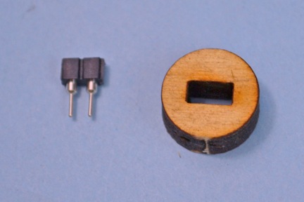
The bulkhead of the piston head I laser-cut from 1/4 inch thick plywood. The rectangle in the center is sized to fit the SIP pin connectors. I like to have a press fit tolerance, so that I can secure it in place with a drop of thick CYA glue.
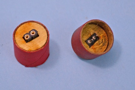
The bulkhead is then glued into a tube coupler with CYA glue. In the 2nd photo, I actually have two SIP pin connectors in the bulkhead. The upper one on the front of the piston head is removable. So when it gets coated with crud, I pull it out with a pair of plyers, and insert a new connector.
The piston heads shown here are for BT-5 size engines. For the 10.5mm motors, I didn’t use any coupler. The plywood disk was the entire piston head.
The nice thing, is these are cheap and quick to make. You can reuse them if you want, by cleaning them between flights. But for the WSMC, I had the girls just toss the tube and the piston heads into the recycle box. We eventually reused the 32″ long piston tubes on some of the final flights of the contest, but we always used a fresh piston head. I think I took about 40 of them to Bulgaria – and the entire batch took less than an hour to assemble.
In the photo above, the piston head on the right has been used. You can see that the bottom is a little sooty. So there is some leakage of gas around the head. This is easily solved by wrapping tape around the coupler to tighten up the fit.
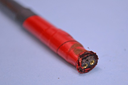
This is a photo of the top of the internal rod. You can see another SIP-connector is mounted here. The piston head simply plugs into this socket.
This is the final layout of the parts in the floating head piston.
The igniter is plugged into the first connector. This is then plugged into the piston head (remember, there is another socket buried in the plywood bulkhead).
Then the whole piston head is connected to the socket that runs through the piston tube.
I used a 1/4 inch diameter graphite tube for the wires. The reason is that you can get them in 36″ long lengths, so you can use a long piston tube. They are stiff enough too — you don’t have to worry about them bending, like an aluminum tube can.
At the back end of the paper piston tube, I glue another coupler or centering ring to act as the piston stop. As with any floating head piston, as the tube fills up with gas, the rocket rises upward. When the piston head slides to the stop, the SIP pin connector just yanks itself out. I really like these, because they make good electrical connection, but still can pull out relatively easy.
Before you get the idea that I invented this, let me say that the credit goes to Chan Stevens. He showed me the design last year at NARAM-55. The only change I made was to laser-cut the bulkhead disk.
A word of caution. NEVER use the graphite rod with the socket end to push out the couplers from the piston tube after the flight is over. There is a chance that you could get one of the pins to break off inside the socket. This is exactly what happened to our piston on Monday (the first day of flying). I was fortunate to borrow a soldering iron from the engine test guys on the field. I had to replace the socket on the end of the graphite rod. Had they not been so nice, the girls would have had to fly the rockets without a piston launcher.


